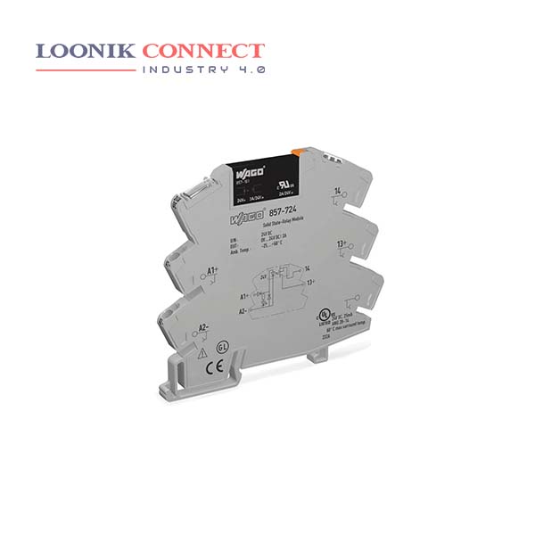
A Solid State Relay (SSR) is a relay that does not have a moving contact. In terms of operation, SSRs are not very different from mechanical relays that have moving contacts. SSRs, however, employ semiconductor switching elements, such as thyristors, triacs, diodes, and transistors. a power relay module is an electrical switch that is operated by an electromagnet.
The electromagnet is activated by a separate low-power signal from a micro controller. When activated, the electromagnet pulls to either open or close an electrical circuit. The main function of the solid state relay is electronic switch, and the solid state module is used to adjust the load power, and voltage regulation.
Connect (R) positive terminal to the push button switch. Connect (R) negative terminal to the negative terminal on battery 1. Connect (L) positive terminal to the positive terminal on battery 2. Connect (L) negative terminal to the positive terminal on load. There are three main types of solid state relay isolation methods used in SSRs, i.e., optical, transformer, and reed.


