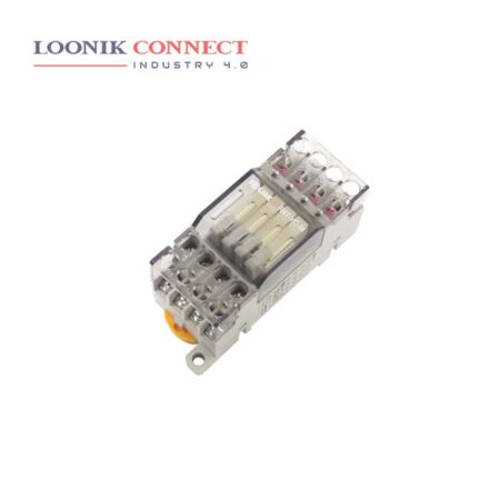
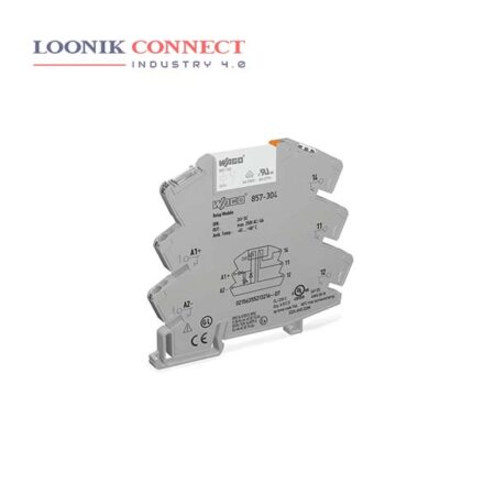
In industrial applications, an optocoupler module is a standalone DIN rail-mounted device imparting optical separation for a signal path. At its core is an optocoupler — a circuit featuring a light-emitting diode or LED and a photosensitive device. A current is first applied to the Optocoupler, which makes the infrared LED emit a light that’s proportional to the current. When the light hits the photosensitive device, it switches on and starts to conduct a current as any ordinary transistor might.
The operation principle of an opto-isolator is Of course, one chooses an emitter which well matches the spectral response of the receiver. Works very fast. Less noise. The optocoupler works well on either AC or DC high-voltage signals. It is also used in a number of sensor applications to sense the presence of physical objects.
An optocoupler is used as input interface. It is a function of insulation and adaptation. A relay is used as output interface. It is voltage adaptation and it allows more power. The power optocoupler is used when the number of operations is important.


